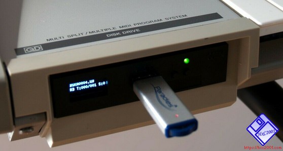
QuickDisk Emulation support
Last modified: 16 January 2026
The HxC Firmware for Gotek drives supports the QuickDisk floppy emulation since the version 3.4.0.0.
To use it, update the Gotek with the HxC Floppy Emulator QuickDisk firmware present in the "Firmwares_Updates/Generic_Gotek/QuickDisk_Firmware/" folder in the firmware archive. (See Firmware update)
A blank .QD floppy disk file image can be found in the firmware archive in the "QuickDisk_Firmware" folder. You can initialize/format this image with your QD machine.
-
The Floppy Emulator Quickdisk pinout assignation is :
Floppy Emulator QD pinout signals assignation :

                -- Shugart pin --          -- QuickDisk Signal function --

                Pin  2 (/DC)           ->  /MS (/MediaSense)
                Pin 10 (/DS0)          ->  Connect it to GND/VSS
                Pin 16 (/MotorOn)      ->  /MO
                Pin 20 (/Step)         ->  /RS (/Reset)
                Pin 22 (/WriteData)    ->  /WD (/WriteData)
                Pin 24 (/WriteGate)    ->   WG (WriteGate)
                Pin 28 (/WriteProtect) ->   WP (WriteProtect)
                Pin 30 (/ReadData)     ->   RD (ReadData)
Pin 34 (/Ready) -> /RY (/Ready)-
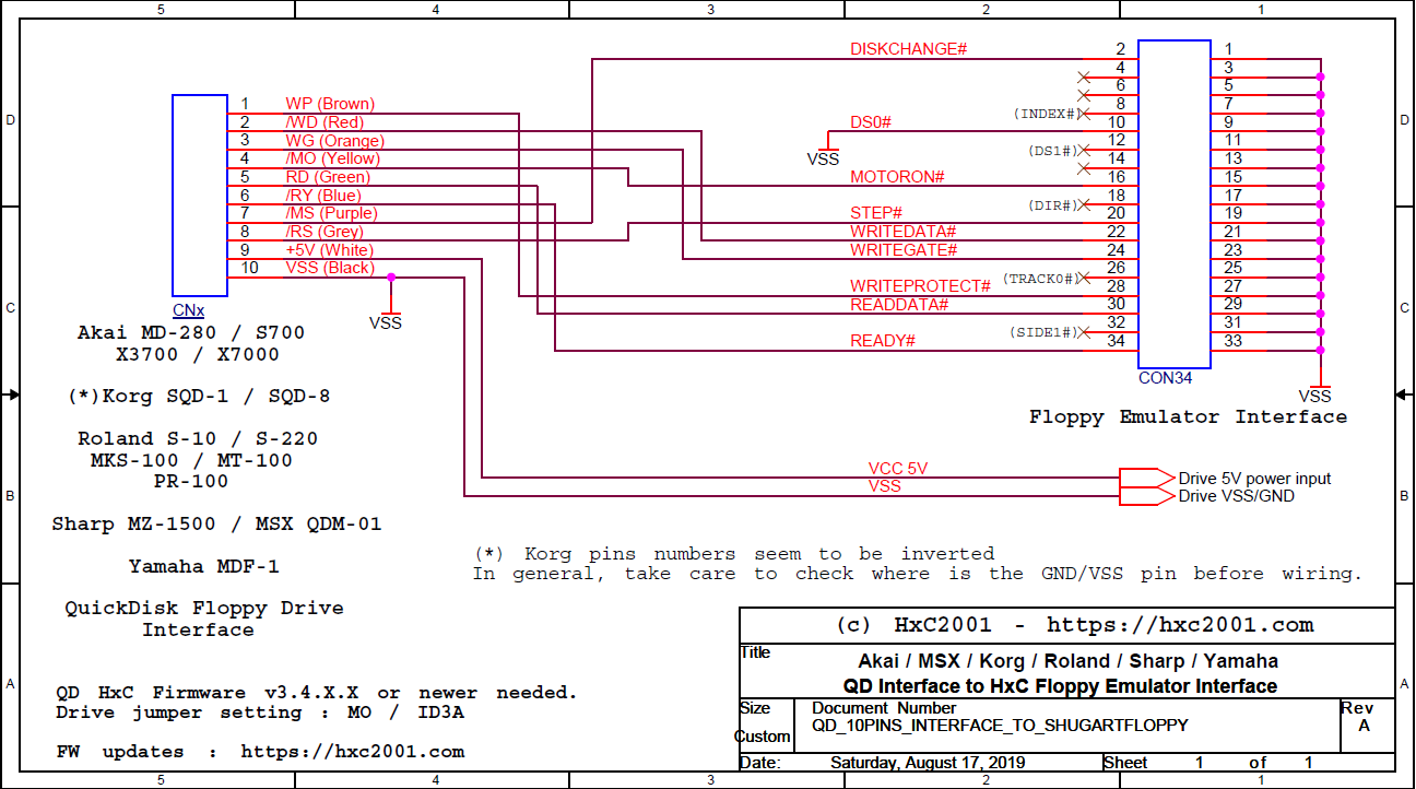
The wiring to follow between the floppy emulator and a 10 pins QuickDisk machine is :
                -- Shugart Floppy Emulator pin --          -- 10 pins QuickDisk machines --

                Pin  2 (/DC)                        ->     QD Pin 7 : /MS (/MediaSense)
                Pin 16 (/MotorOn)                   ->     QD Pin 4 : /MO (/Motor ON)
                Pin 20 (/Step)                      ->     QD Pin 8 : /RS (/Reset)
                Pin 22 (/WriteData)                 ->     QD Pin 2 : /WD (/WriteData)
                Pin 24 (/WriteGate)                 ->     QD Pin 3 : WG (WriteGate)
                Pin 28 (/WriteProtect)              ->     QD Pin 1 : WP (WriteProtect)
                Pin 30 (/ReadData)                  ->     QD Pin 5 : RD (ReadData)
                Pin 34 (/Ready)                     ->     QD Pin 6 : /RY (/Ready)
                PSU Pin 1 (+5V)                     ->     QD Pin 9 : +5 Volts
PSU Pin 2 (VSS/GND) -> QD Pin 10: VSS/GND-
The wiring to follow between the floppy emulator and a 12 pins Mitsumi QuickDisk machine is : NOTE: The Nintendo FDS use a different pinout !
                -- Shugart Floppy Emulator pin --          -- 12 pins Mitsumi QuickDisk machines --

                Pin  2 (/DC)                        ->     QD Pin 3 : /MS (/MediaSense)
                Pin 16 (/MotorOn)                   ->     QD Pin 10: /MO (/Motor ON)
                Pin 20 (/Step)                      ->     QD Pin 6 : /RS (/Reset)
                Pin 22 (/WriteData)                 ->     QD Pin 8 : /WD (/WriteData)
                Pin 24 (/WriteGate)                 ->     QD Pin 9 : WG (WriteGate)
                Pin 28 (/WriteProtect)              ->     QD Pin 5 : WP (WriteProtect)
                Pin 30 (/ReadData)                  ->     QD Pin 4 : RD (ReadData)
                Pin 34 (/Ready)                     ->     QD Pin 7 : /RY (/Ready)
                PSU Pin 1 (+5V)                     ->     QD Pin 2 : +5 Volts
                PSU Pin 2 (VSS/GND)                 ->     QD Pin 1 : VSS/GND
                PSU Pin 3 (VSS/GND)                 ->     QD Pin 12: VSS/GND
Pins 4,6,8,12,14,18,26 and 32 can be left unconnected on the Gotek. Odd pins Gotek pins (1,3,5,7,…,33) should be connected to the VSS/GND.
The jumper must be set to "MO".
Below you can found the QuickDisk Floppy Drive Interface to the floppy emulator wiring schematic for the following machines :
-
Akai MD-280(S612).
[Tested and working !]
-
Akai 700.
[Tested and working !]
-
Akai X3700
-
Akai X7000.
[Tested and working !]
-
Korg SQD-1 / SQD-8
-
Roland S-10.
[Tested and working !]
-
Roland S-220.
[Tested and working !]
-
Roland MKS-100.
[Tested and working !]
-
Roland MT-100.
[Tested and working ! Beware ! this one use a mirrored Mitsumi pinout !]
-
Roland PR-100.
[Tested and working ! Beware ! this one use a mirrored Mitsumi pinout !]
-
Sharp MZ-800.
[Tested and working !]
-
Sharp MZ-1500
-
MSX QDM-01
-
Yamaha MDF-1
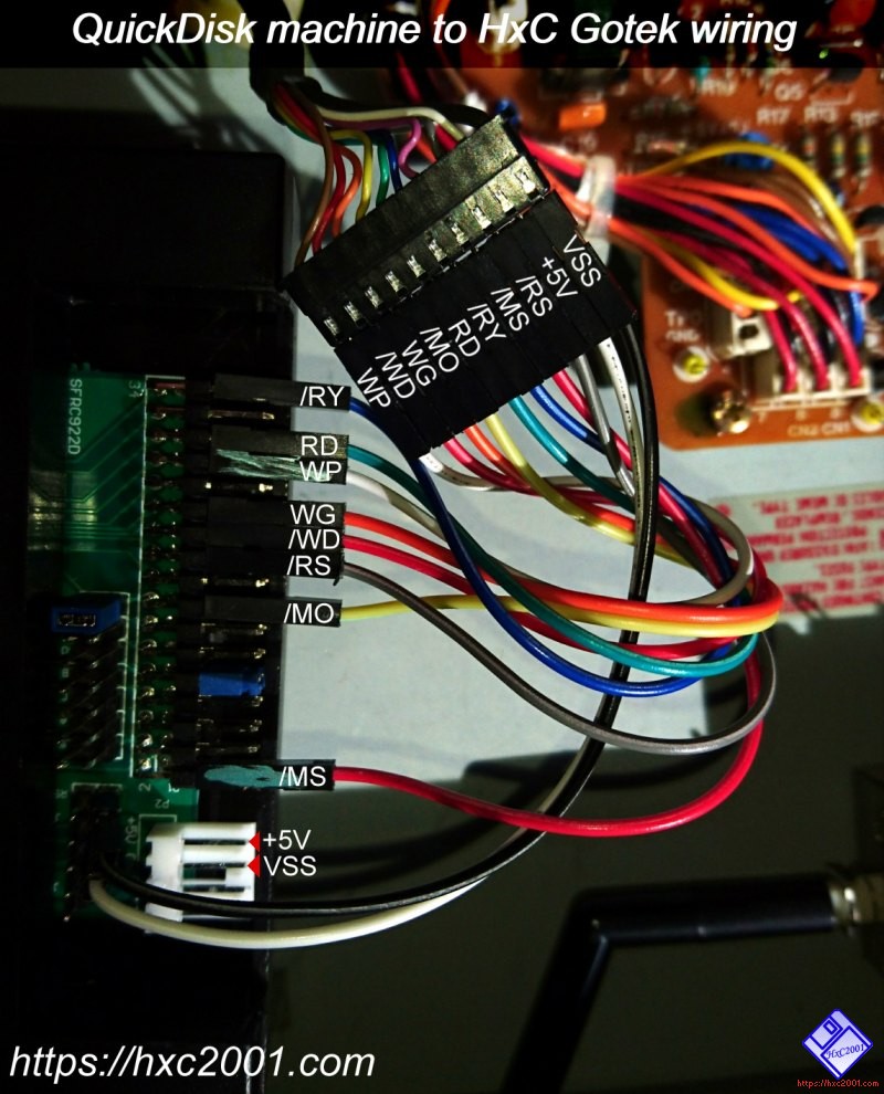
The wiring can be done without soldering on most machines. Below an example of wiring done with "Jumper cables" :
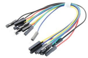
Here it is the typical male to female jumper cables you can use :
If you have another machine and want to know which wiring you must use, just ask ! :)
Last modified: 16 January 2026
| HxC Floppy Emulator project | Legal Mentions | (C)2006-2026 HxC2001 / Jean-François DEL NERO |