I2C LCD Screen Add-on
Last modified: 16 January 2026

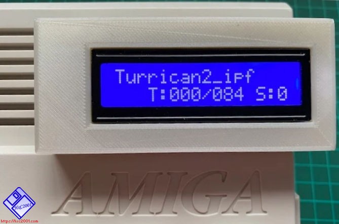
You can connect an I2C 16x2 characters LCD screen to the Gotek display port.

These kind of I2C LCD board is compatible with the firmware :
https://www.ebay.com/itm/IIC-I2C-TWI-SP-I-Serial-Interface-Board-Module-Port-For-Arduino-1602LCD-Display-/310565362720?pt=LH_DefaultDomain_0&hash=item484f235c20 (board only - without the LCD)
https://www.ebay.com/itm/IIC-I2C-TWI-SPI-Serial-Interface-Board-Module-Port-for-Arduino-1602LCD-Display-/161245616356?pt=LH_DefaultDomain_0&hash=item258afcd8e4 (board only - without the LCD)
Any I2C address is supported : The firmware scan automatically the I2C bus at power up (0x20-0x27 and 0x38-0x3F address range scanned) So there is no specific requirement about the I2C address setting.
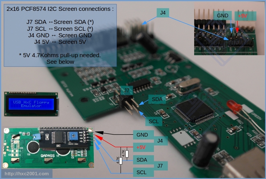
To connect the I2C LCD, you have to connect SDA & SCL at the J7 connector (see below). Please note that 2 additional 4.7Kohms pull up resistors (+5V) are needed on SCL & SDA. the +5V and GND wire can be connected on the programming connector (see below) :
If you want to build the I2C board yourself, here is the schematic: Ext_Slim_HxC_Floppy_Emulator_I2C_LCD_Schematic.pdf
-
Possible +5V source on the PCB (on the programming connector):
 _____________________________
 |
-+--- NC
-+--- GND      O J3 (BOOT0)
-+--- GND      O VCC3V3
-+--- +5V     OO TX
 |        +5V OO RX
 |        GND OO RST
 |--
 |  |
| |-
SCL & SDA position on J7 :
                           _____|
                          |     |
                          | USB |
                          |_____|
        OO______________________|
    SDA OO|SCL
    GND OO|VCC3V3
        J7|
          |
__________|
Last modified: 16 January 2026
| HxC Floppy Emulator project | Legal Mentions | (C)2006-2026 HxC2001 / Jean-François DEL NERO |