Note : All data on this page are subject to changes without prior notice !
PDF version :HxC_Floppy_Emulator_HFE_file_format.pdf
29 November 2010 - v1.0 : Initial version.
20 June 2012 - v1.1 : Add single_step, track0s0/1_altencoding and track0s0/1_encoding header fields.
8 July 2012 - v2.0 : Add opcodes support in stream (HFEv2).
4 August 2017 - v3.0 : Opcodes redefinition/redesign.
22 May 2019 - v3.1 : Add weakbits support on HFEv3.
The HFE file format is a simple floppy bitstream tracks container originally designed for the SD HxC Floppy Emulator devices. It stores the floppy media content at the bit-cell level.
HFE is the acronyme of HxC Floppy Emulator.
The HxC Floppy emulators are a series of universal floppy emulators.
This format was originally designed for these emulators. (See https://hxc2001.com)
There are many floppy image formats for every system family. Supporting all of them in a floppy emulator increase the firmware complexity and the higher the firmware complexity, the more difficult it is to read the code and maintain it, and the higher the likelihood of faults and defects. In addition to that, some of these formats cannot be supported without increasing hardware cost (Example: Compressed formats that need a lot of RAM to be unpacked).
Beside this, most of these formats are missing some critical information to emulate or reproduce the floppy media properly: Most of them don't store the low-level disk layout and encoding informations. You then need to setup a kind configuration file to tell the emulator how to read them. The emulator developer can also make some guessing functions to load them, which can be prone to error, especially when you target a large set of machines.
The HFE format is a new MFM/FM or GCR encoded floppy file image format. The HFE format keeps intact all the informations present on the floppy disks : Sectors metadata and data, error detection codes (CRC), all gaps and so on. Unlike the older raw data images like IMG, this file format is designed to support most of the existing floppy formats and keeps intact all the floppy format metadata. No more guessing or configuration needed to be able to read the images !
From a safety and data integrity point of view, the HFE keeps intact and doesn't bypass the original disk controller data integrity checking mechanisms. The machine still able to check that the data loaded from the flash memory media (USB, SDCard...) is valid. The full data path still protected by the original sectors checksums.
To sum up : The HFE store the low level bits present on the floppy media, and this make it particulary accurate to emulate most of the floppy formats.
The HFE file format contains a file header with metadata like the number of tracks in the file, track format ID, floppy interface configuration...
The second part is a tracks offsets and sizes array.
And finally all the tracks bitstream buffers.
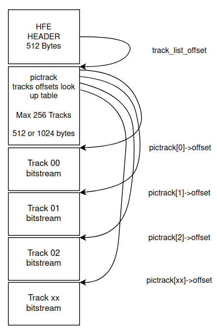
First part : 0x0000-0x0200 (512 bytes) : HFE header
	typedef struct picfileformatheader_
	{
		/*0x000*/	uint8_t		HEADERSIGNATURE[8];		// "HXCPICFE" for HFEv1 and HFEv2, "HXCHFEV3" for HFEv3
		/*0x008*/	uint8_t		formatrevision;			// 0 for the HFEv1, 1 for the HFEv2. Reset to 0 for HFEv3.
		/*0x009*/	uint8_t		number_of_track;		// Number of track(s) in the file
		/*0x00A*/	uint8_t		number_of_side;			// Number of valid side(s) (Not used by the emulator)
		/*0x00B*/	uint8_t		track_encoding;			// Track Encoding mode (Used for the write support - Please see the list above)
		/*0x00C*/	uint16_t	bitRate;			// Bitrate in Kbit/s. Ex : 250=250000bits/s, Max value : 1000
		/*0x00E*/	uint16_t	floppyRPM;			// Rotation per minute  (Not used by the emulator)
		/*0x010*/	uint8_t		floppyinterfacemode;		// Floppy interface mode. (Please see the list above.)
		/*0x011*/	uint8_t		dnu;				// Reserved
		/*0x012*/	uint16_t	track_list_offset;		// Offset of the track list LUT in block of 512 bytes (Ex: '1' means offset 0x200, '2' means 0x400 ...)
		/*0x014*/	uint8_t		write_allowed;			// 0x00 : Write protected, 0xFF: Unprotected

		// v1.1 addition - Set them to 0xFF if unused.
		/*0x015*/	uint8_t		single_step;			// 0xFF : Single Step - 0x00 Double Step mode
		/*0x016*/	uint8_t		track0s0_altencoding;		// 0x00 : Use an alternate track_encoding for track 0 Side 0
		/*0x017*/	uint8_t		track0s0_encoding;		// alternate track_encoding for track 0 Side 0
		/*0x018*/	uint8_t		track0s1_altencoding;		// 0x00 : Use an alternate track_encoding for track 0 Side 1
		/*0x019*/	uint8_t		track0s1_encoding;		// alternate track_encoding for track 0 Side 1
	}picfileformatheader;
Notes :
- uint16_t fields are in little endian format (LSB first).
- Unused header bytes must be set to 0xFF.
- The header structure must be packed.
		#define IBMPC_DD_FLOPPYMODE				0x00
		#define IBMPC_HD_FLOPPYMODE				0x01
		#define ATARIST_DD_FLOPPYMODE				0x02
		#define ATARIST_HD_FLOPPYMODE				0x03
		#define AMIGA_DD_FLOPPYMODE				0x04
		#define AMIGA_HD_FLOPPYMODE				0x05
		#define CPC_DD_FLOPPYMODE				0x06
		#define GENERIC_SHUGGART_DD_FLOPPYMODE			0x07
		#define IBMPC_ED_FLOPPYMODE				0x08
		#define MSX2_DD_FLOPPYMODE				0x09
		#define C64_DD_FLOPPYMODE				0x0A
		#define EMU_SHUGART_FLOPPYMODE				0x0B
		#define S950_DD_FLOPPYMODE				0x0C
		#define S950_HD_FLOPPYMODE				0x0D
		#define DISABLE_FLOPPYMODE				0xFE
		#define ISOIBM_MFM_ENCODING				0x00
		#define AMIGA_MFM_ENCODING				0x01
		#define ISOIBM_FM_ENCODING				0x02
		#define EMU_FM_ENCODING					0x03
		#define UNKNOWN_ENCODING				0xFF
Note :
If track0s0_altencoding is set to 0xFF, track0s0_encoding is ignored and track_encoding is used for track 0 side 0.
If track0s1_altencoding is set to 0xFF, track0s1_encoding is ignored and track_encoding is used for track 0 side 1.
Second part : (up to 1024 bytes) : Track offset LUT
	typedef struct pictrack_
	{
		uint16_t	offset;		// Track data offset in block of 512 bytes (Ex: 2 = 0x400)
		uint16_t	track_len;	// Length of the track data in byte.
	}pictrack;
A 82 tracks disk the pictrack table use 82 entries.
Pictrack[82];
Note :
uint16_t fields are in little-endian format.
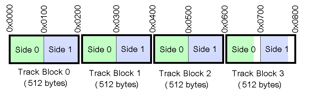
Third part : Track data
A track data contains a track bitstream. Each bit represent is a cell state. A track can contain a MFM / FM / GCR or a custom encoding.
The track is divided in 512 Bytes blocks and each block contains a part of the Side 0 track and a part of the Side 1 track:
The bits transmission order to the FDC is LSb first :
Bit 0-> Bit 1-> Bit 2-> Bit 3-> Bit 4-> Bit 5-> Bit 6-> Bit 7->(next byte)
Transmission rate cell rate = Header bitrate * 2
Cell time = 1 / (Header bitrate * 2)
Note :
The bitstream content is specific to each targeted system and disk format !
The low level floppy disk controller track and sectors formats descriptions is not covered by this document !
For more floppy disks related informations, please have a look to these documentations : https://hxc2001.com/download/datasheet/floppy/thirdparty/
HFE variants v2 and v3 support opcodes into the tracks bitstreams. These opcodes make possible to reproduce "variable bitrate" area, weak/fuzzy bits and other types of particularities of certain disks.
Regarding the file structure, apart from the "formatrevision" and "HEADERSIGNATURE" fields, these variants are structurally identical to HFEv1.
The opcodes insertion allows the modulation of the bitrate, the generation of "weak bits", and compensate the 2 sides timings. The hfev3 encoder inserts these different opcodes in the track at regular intervals in order to reach the areas average bitrate of the original disc and to compensate the temporal shifts between sides 0 and 1 generated by the bitrate sides differences and opcodes insertion.
This general principle was used for the first time in the USB HxC Floppy Emulator from 2008. It was then implemented in the SD HxC Floppy Emulator with HFEv2 and then transposed to the HxC Floppy Emulator firmware for Gotek in HFEv3.
Note :
For conventional, industrial and medical usages, it is recommended to not use these variants. They were designed for specific use cases and still in experimental state !
The HFE v2 is basically the same format as the HFE v1. It just add 4 bytes opcodes support.
| Opcode | Encoding | Description |
|---|---|---|
| SET BAUDRATE | 0x00 0x01 BR XX | Set bitrate BR = PIC18F SPBRG Register |
| RANDOM | 0x00 0x02 RD XX | Generate random pulses during 8 cells. |
| DATA OPCODE | 0x00 0x03 DD XX | Transmit arbitrary data "DD". |
| SET INDEX STATE | 0x00 0x04 II XX | Set/Clear the index signal according to the "II" bit 0 state. |
| NOP | 0x00 0x05 XX XX | Do nothing - used to align side 0 and side 1 stream. |
| BREAK BUFFER | 0x00 0x06 XX XX | Jump to the next 512 bytes track buffer. |
| SET WRITEMODE | 0x00 0x07 WM XX | Change / select the track write mode. |
The HFEv3 is an optimized version of the HFEv2 : Opcodes are shorter and easier to decode.
| Opcode | Encoding | Description |
|---|---|---|
| NOP | 0xF0 | Do nothing |
| SET INDEX | 0xF1 | Start an Index pulse. |
| SET BITRATE | 0xF2 0xBB | BB : Cells-rate in k/samples per seconds. |
| SKIP BITS | 0xF3 0xLL | Skip "LL" bits (0-7) |
| RAND | 0xF4 | Do nothing - used to align side 0 and side 1 stream. |
| -- Reserved -- | 0xFF | -- Reserved -- |
| HxC Floppy Emulator project | Legal Mentions | (C)2006-2026 HxC2001 / Jean-François DEL NERO |