Gotek hardware I/O lines diagnostic/test firmware
Last modified: 22 February 2025
Since the Gotek floppy emulator is quite sensitive to ESD and other electrical issues, the floppy lines can be easily damaged.
This special firmware allows you to test/check all Gotek’s Input/Output lines with a simple wire. The test must be run with floppy ribbon disconnected from the machine. Once enabled/flashed with the diagnostic firmware, all outputs will toggle every 2 seconds.
All inputs states are displayed on the screen.
This firmware can be found in the Diagnostic_Firmware folder in the firmware archive.
Input lines test method
The default input states should be High (1), so to test an input line you have just to connect it to the ground/vss. On the floppy port you can use a jumper to make a contact between the input line and the ground (See floppy port pinout). Once the jumper is placed between the line pin and the ground/vss pin the corresping input state should turn to Low (0).
Output lines test method
All outputs are toggling every 2 seconds during the test.
|
Note
|
A 1 ms pulse is sent to the JB output at each toggle to test the buzzer ouput. |
Connect the output line to test to one input line (use a tested input by the above method) with a simple wire. If the corresponding input status is toggling with the outputs line, then this means that the output line/driver is working properly.
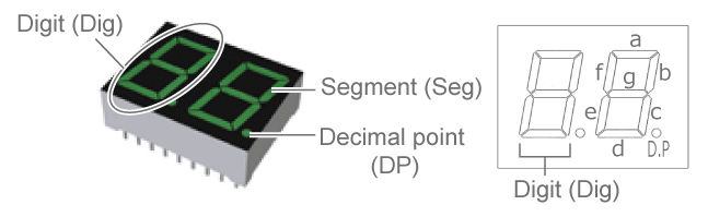
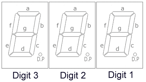
LCD / OLED / 7 segments screens output/input status definition
LCD/OLED input lines status format : "IN:123456 789AB"
Digit |
Pin |
1 or Digit-1-segment-a |
Floppy Drive Select line (Pin 10 if S0 is set, Pin 12 if S1 is set or Pin 16 if MO jumper is set). |
2 or Digit-1-segment-b |
Floppy -Direction In (Pin 18) |
3 or Digit-1-segment-c |
Floppy -Step (Pin 20) |
4 or Digit-1-segment-d |
Floppy -Write Data (Pin 22) |
5 or Digit-1-segment-e |
Floppy -Write Enable (Pin 24) |
6 or Digit-1-segment-f |
Floppy -Head 1 Select (Pin 32) |
7 or Digit-1-segment-g |
Down push button (left) |
8 or Digit-2-segment-a |
Up push button (right) |
9 or Digit-2-segment-b |
Select push button (JA) |
A or Digit-2-segment-c |
Rotary CK (J7-2) |
B or Digit-2-segment-d |
Rotary DIR (J7-1) |
7 Segments Digit-3 |
h when the outputs are high and L the outputs are low. |
7 Segments Digit-2-segments e,f & g |
ON when the outputs are high and OFF the outputs are low. |
Floppy connector pinout
Pin |
Signal |
Pin |
Signal |
01 |
Ground |
(O)02 |
-High Density Select |
03 |
Ground |
04 |
Reserved |
05 |
Ground |
06 |
Reserved |
07 |
Ground |
(O)08 |
-Index |
09 |
Ground |
(I)10 |
-Drive Select 0 (*) |
11 |
Ground |
(I)12 |
-Drive Select 1 (*) |
13 |
Ground |
14 |
Reserved |
15 |
Ground |
(I)16 |
-Motor Enable (*) |
17 |
Ground |
(I)18 |
-Direction In |
19 |
Ground |
(I)20 |
-Step |
21 |
Ground |
(I)22 |
-Write Data |
23 |
Ground |
(I)24 |
-Write Enable |
25 |
Ground |
(O)26 |
-Track 0 |
27 |
Ground |
(O)28 |
-Write Protect |
29 |
Ground |
(O)30 |
-Read Data |
31 |
Ground |
(I)32 |
-Head 1 Select |
33 |
Ground |
(O)34 |
-Diskette Change/Ready |
(*)Depend on the S0/S1/MO jumper!
7 segments screen segments definition
Last modified: 22 February 2025
| HxC Floppy Emulator project | Legal Mentions | (C)2006-2025 HxC2001 / Jean-François DEL NERO |